Eric Lundquist‘s Mobile Robotic Platform was an experimental built-from-scratch design with several unique features. Its behavior was very moth-like in that it chased the brightest light that it could detect. Obstacles were detected and avoided with feeler wires on 3 sides.
The brains of the Mobile Robotic Platform were a Parallax BASIC Stamp I providing 8 I/O lines and programming in a dialect of BASIC. Eric added a Stamp Extender that provided an additional 16 I/O lines.
The BASIC Stamp drove the motor and direction relays, the LEDs, and the Piezo buzzer. It also monitored the status of bumpers and polled light levels from its 3 photocell “eyes”.
The base was painted pine shelving material. Not only was this low cost, it did not require any specialized tools to work aside from a circular saw. It also made it exceptionally easy to mount, fasten, and rearrange things.
Eric’s ultimate goal with this project was to add several more BASIC Stamp controllers to make a distributed parallel architecture. This would have allowed more complex behavioral responses and interactions with the environment.
Category: History
Negative Head
[Editor’s note : This information was extracted from an entry in an old version of The Robot Group web site archived by the Wayback Machine on 1996-12-04. Sorry, no photographs have emerged to-date.]
Negative Head is another face character for the planned robot theatre performance being directed by Brooks Coleman. The Negative Head is made from street lamp parts and servos. It creates face movements by overlaying transparent patterns to grids.
Arthur … The Door Butler
Leon Hubby proposed this project.
Description
“Arthur … The Door Butler will resemble a very normal door. As you approach, you will see a door mounted in a partial wall with a very standard motion detector mounted at the top and a porch light to the side. A welcome mat will greet the visitors.”
Operation
“As the visitors approach, the motion detector will turn on the porch light and enable the door to greet the individuals. When the visitors step on the welcome mat, Arthur will open and then close the door for them. First, a compartment on the side of the door will open, a robotic arm will unfold, raise itself, and position to grasp the door knob. Arthur will then grab the door knob, rotate it, and open the door. A mat on the other side of the door will signal Arthur that the individual has passed through. The arm will then close the door, release its grip, and refold itself up closing its access door. “
Artistic and Technological Content
“Art, as they say, is in the eye of the beholder. From my perspective the door represents a sculpture in motion. The image of an automatic door does not invoke much artistic impression. A door that lends a hand and opens itself, however, tends to be a bit more intriguing, if not novel. The technological content is centered around making a light-weight yet strong arm and gripper. This project will explore the use of different sensors to detect individuals, the door knob, etc. Differing techniques will be used to center the gripper on the door knob, close around the knob, and rotate to open it. This project will also explore the control aspects using the HC11E9. Special efforts and attention will be placed on the construction of the arm in order to build a light-weight, strong arm. The arm will be constructed of either PVC pipe or Styrofoam coated with epoxy fiberglass.”
RoboVision

RoboVision was a quick virtual reality (VR) project by Tom Davidson and Sonia Santana. The aim of the project was to provide attendees at RoboFest 7 a feel for what a robot’s vision might be like.
The project’s components were two VictorMaxx Stuntmaster VR headsets which had their video inputs wired to Supercircuits microcameras. The Stuntmaster had a single camera screen. The microvideo camera was mounted on the outside of the head gear with the battery power unit worn as a belt pack. An on/off timer switch was been wired to the helmet to allow more participants equal access. The entire head unit was covered with a cardboard mask design similar to that of the Megabot Army for a cool robot head appearance.
There was ample room in the head gear to allow for downward vision so that the person wearing the helmet could walk around and avoid tripping over stuff. The camera images that were projected into the headset screen were feeds from various mobile robots such as Commander Salamander and Mobile Platform and Dweebvision.
Mobile Platform
Editor’s note : The contents of this page were extracted an archived entry found on the Internet Archive’s Wayback Machine. The page, originally on Carlos Puchol’s web space at The University of Texas – Austin, was archived on 1996-12-31.
Introduction to the Mobile Platform
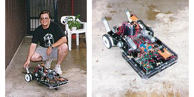
The mobile platform project is designed to provide ground-based mobility to experimental sensor and control systems, allowing them to traverse level surfaces such as building floors, and possibly streets and backyards. Think of it as a Hero robot on steroids.
Mobile Platform Mechanical System
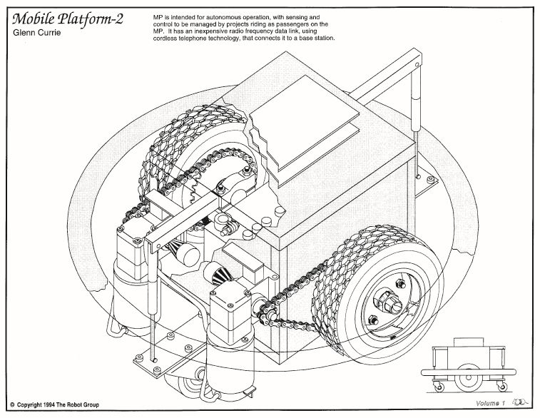
The mobile platform is supported by two main drive wheels, with stability augmented by fore and aft caster wheels. Depending on distribution of weight in the platform and payload, it may be self-righting through balancing about the main wheel axis. Possible caster wheel heights are bounded on the low end by the need to negotiate unlevel surfaces and, on the high end, by the need to maintain the platform more or less level during dynamic maneuvers. Caster wheel mounting heights and possibilities for controllable height adjustments need to be investigated.

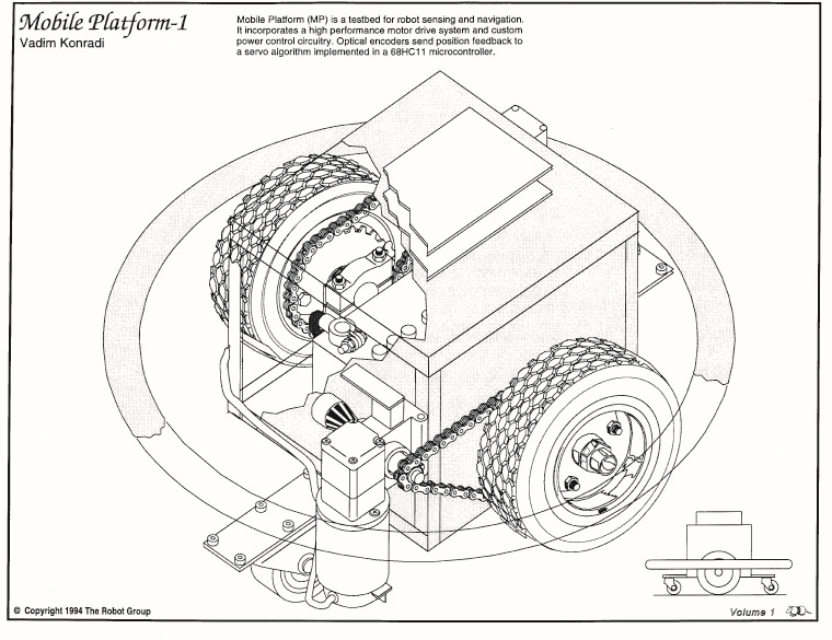
Vadim Konradi's Mobile Platform
Vadim Konradi's Mobile Platform

Vadim Konradi's Mobile Platform
Vadim Konradi's Mobile Platform
The vehicle platform is designed to fit within a 2-foot circle so it can navigate doorways and turn within its width. Currently equipped main wheels are 11.5 inches high. The platform structure is made up of 1-inch square steel tubing in a box structure. Vertical hard clearance when level is 2 inches. The top of the box structure is 12 inches above the floor. In general, platform structure below the 12 inch height is intended to be dedicated to platform mechanicals, and passenger equipment will mount to the top surface. The upper surface consists of a perimeter structure of 1-inch square tube, 10 inches wide by 11 inches fore-aft. We will equip it with mounting holes or tabs, or studs, or tape things on top with duct tape.
Platform main wheels are driven from wheelchair motors via #35 roller chain. Based on preliminary observations, motive force of the system will be limited primarily by tire friction. Based on measured motor torque of _____, and a _____ : _____ reduction ratio, the horizontal stall force will be _____. Thus a heavily-loaded platform will be able to push over or drive through certain static objects. Some motor current sensing or other safety mechanisms may be appropriate. A perimeter bumper system with contact switches will likely be installed eventually.
Mobile Platform Electrical / Electronic System
The mobile platform electronics are designed for control via a Motorola 68HC11 microcontroller Evaluation Board (EVB). The EVB receives movement commands from a higher authority and performs the necessary control functions to drive the platform motors. The EVB has been used as a basis because it is a handy development system. Eventually the motor drive circuit board will probably have an on-board HC11.
Control is currently passed to the EVB via a standard serial port for testing in conjunction with a data terminal. Eventually control will be migrated to the HC11 Serial Communications Interface (SCI) for interprocessor communication.
The motor drive power electronics reside on a circuit board with the same dimensions as the EVB and similarly placed 60-pin connector. It is capable of being mounted, with a suitable connector, as a daughter board on top of the EVB. Logic and motor drive circuitry are separate, with optical coupling of control and status signals in both directions. Motors are controlled via enable and direction signals. The enable is pulse width modulated (PWM) to control motor speed. In addition to the individual motor enables, a global driver enable allows shutdown of the entire power output stage. An overcurrent sense signal is sent back from the motor driver circuit to the HC11.
Each motor driver consists of four MOSFET transistors in an H-bridge configuration, controlled by a _____ IC. The most recent circuit version is equipped with IRF540 MOSFETS, giving it current capability of 27 A continuous, 108 A peak. This appears to be a reasonable transistor size for efficient operation at anticipated motor power levels. MOSFETS with higher current ratings may be substituted as required. The motor driver circuit is currently programmed for overcurrent limit of approximately 20 A, which may be modified by changing the current sense shunt.
Optical encoders on the motor output shafts are used to feed back motor position to the HC11. Each encoder consists of a pair of optical interrupters and an encoder wheel. The encoder sensors use a Schmitt trigger buffer to control encoder hysteresis. Optical encoder outputs are fed to the HC11 via connectors on the motor driver board. Connectors are 4-pin .100 type.
The motor driver circuit board is designed to operate with input voltage in the 5V-30V range. Full turn-on saturation of the MOSFETS is not guaranteed below 10V, so operation is not recommended in this range with a large motor load. Power connectors on the power board are Molex .093 series 2-pin connectors, connecting to male connectors on batteries and female connectors on motors. The motor drive circuit is fused with a standard automotive type fuse. The fuse should protect against melted wires and boiling batteries in the event of an output short. Current limiting by the transistor driver IC should protect the MOSFETs to some degree. This will no doubt be determined experimentally at some time.
There is an undesirable and potentially exciting design defect on the current version of the power board, resulting in runaway full-speed drive of the motors when power is removed from the control logic. This will be corrected on future versions. For the moment, it is necessary to ensure that logic power is applied prior to application of motor drive voltage, and motor drive voltage disconnected prior to disconnection of logic power.
Control Algorithm
General
The HC11 program which controls platform motion is mainly interrupt-driven. Encoder transitions are serviced as they occur. A real-time counter schedules updates of the trajectory generator and control loop. PWM transitions are controlled by HC11 internal timers, which are reset at the PWM frequency. Implementations of these functions are more or less similar to HC11 databook examples.
Movement Command Set
Platform movement is directed through commands to the HC11 via the serial port. The following is a summary of currently implemented commands :
- Calibrate – sets setpoint position equal to current position (overrides move in progress)
- Translate (direction,magnitude) – forward or reverse increment to current setpoint position
- Rotate (direction, magnitude) – rotates right or left about platform centerline
- Velocity (direction, magnitude) – gives platform velocity in specified direction
- Radius (direction, length) – specifies curve radius in conjunction with velocity commands
- Motor (direction, magnitude) – allows independent increments topology motor setpoints
- Control (various parameters) – allows resetting of control equation constants and limit values
“Magnitude”, a parameter in many commands above, is expressed in terms of encoder counts, and the relation to physical movement distance is a function of encoder resolution, gear ratio, and wheel size. Encoders should eventually be sized such that some whole number relation exists between counts and distance in standard units of measure. Radius is specified in increments of half the vehicle track.
Commands as currently implemented return prompt strings to the data terminal. Such information will be omitted for interprocessor control via the SPI.
Wheel Position Settings and Trajectory Generation
Each wheel has an associated destination position counter. The count values are modified through addition and subtraction of increments for instantaneous movements. Velocity commands cause the velocity value to be added to the wheel counts at the trajectory generation timestep interval. When a non-straight path is directed via the Radius command, the destination counts are incremented differently to achieve the desired radius. Operation at large radii is not smooth; the algorithm may be modified someday.
Translation, rotation, and velocity commands may be overlaid with predictable, though not always intuitive, results. In general, translation and rotation commands are intended to be applied disjointly, and separately from velocity commands. Velocity and radius commands are intended to be used together in a smooth manner. All commands take effect immediately but translations and rotations modify endpoint positions, whereas velocity and radius commands modify the incremental setting of new endpoints.
Eventual additions to the command set may include profiled moves, consisting of acceleration, maintained velocity, and deceleration. Other means of limiting acceleration and jerk forces via programmable limits are possible. Another feature, primarily applicable to translation and rotation commands, would be the ability to queue commands, i.e. move forward 5, turn left 2, move forward 8. Eventually the command set will probably need to be divided into two or more distinct modes of operation.
Encoder Sensing and Actual Position Determination
Optical encoders send two digital signals in quadrature to HC11 inputs. Transitions on one signal are recognized, at which point an interrupt routine reads the other signal and determines direction of encoder motion. New position is compared with previous position for the possibility of encoder error which is not really handled correctly right now anyway. Then the wheel position count is incremented or decremented as appropriate.
Generation of Motor Force Function
Voltage applied to each motor is determined via a comparison between destination position and actual position. If there is any difference, the control algorithm exerts force through the motor to drive the error to zero. The position control is implemented in a proportional-integral-derivative (PID) loop, with command-settable gain values for each term. The motor PWM duty cycle is also subject to a command-settable limit. The result of the control calculation is a duty cycle, which is used by the PWM logic to generate a PWM output from the HC11 for the motor driver circuit.
Error / Failure / Problem Resolution
Some work needs to be done in recognizing problems with platform motion such as bumping into objects, motor overcurrent, encoder / drivetrain / wheel slip, etc., and acting on these problems accordingly. The control algorithm will need to shut down activities which are causing problems and report back to its higher authority.
Balancing Act
Since the platform has two wheels, fairly responsive motors, and a dedicated controller, it may be possible to perform active balancing of top-heavy loads without relying on the caster wheels. This is actually not that farfetched, but would require some attitude-sensing hardware and algorithm development. It would also be totally cool.
RoboFest 7
RoboFest 7 was held September 14th and 15th, 1996 at Dobie Mall, Austin, Texas. Dobie Mall was one of the major sponsors of RoboFest 7 and we are grateful to them for their support.
The festival times were 10:00 a.m. to 6:00 p.m. on Saturday and noon to 5:00 p.m. on Sunday. Admission was $4.00 for adults and $2.00 for children under 12 years of age.
The Robot Film Festival, at Dobie Theatre, featured three films with robotic themes. Admission price for each film was $3.50. For more information and descriptions of the films browse the film festival web page.
An official press release was prepared along with lists of the exhibits, the exhibitors, the guest speakers, and the volunteers (without whom none of this would have been possible)
The following businesses were sponsors of RoboFest 7 :

Dobie Mall, an official sponsor of RoboFest 7
Dobie Mall, an official sponsor of RoboFest 7

The Austin Chronicle, an official sponsor of RoboFest 7
The Austin Chronicle, an official sponsor of RoboFest 7

Capital City Container, an official sponsor of RoboFest 7
Capital City Container, an official sponsor of RoboFest 7

Motorola, an official sponsor of RoboFest 7
Motorola, an official sponsor of RoboFest 7

Alternate Audio, an official sponsor of RoboFest 7
Alternate Audio, an official sponsor of RoboFest 7

Zilker Internet Park, an official sponsor of RoboFest 7
Zilker Internet Park, an official sponsor of RoboFest 7

KROX 101, an official sponsor of RoboFest 7
KROX 101, an official sponsor of RoboFest 7
Additional support and in-kind services were provided by :

Additional financial and in-kind support for RoboFest 7 was provided by TechWorks.
Additional financial and in-kind support for RoboFest 7 was provided by TechWorks.

Additional financial and in-kind support for RoboFest 7 was provided by tellabs.
Additional financial and in-kind support for RoboFest 7 was provided by tellabs.

Additional financial and in-kind support for RoboFest 7 was provided by Kinko's.
Additional financial and in-kind support for RoboFest 7 was provided by Kinko's.

Additional financial and in-kind support for RoboFest 7 was provided by Outernet.
Additional financial and in-kind support for RoboFest 7 was provided by Outernet.

Additional financial and in-kind support for RoboFest 7 was provided by Eyecon Interactive Media, Inc.
Additional financial and in-kind support for RoboFest 7 was provided by Eyecon Interactive Media, Inc.
The background material for this page is derived from archived pages (1, 2) on the Internet Archive Wayback Machine
RoboFest 7 Exhibitors

Austin Free-Net is a non-profit corporation providing public access to the Internet and emerging technologies for all Austin residents, especially those who don’t have computers in their homes. The Free-Net is a community-driven project.

CSW Communications, Inc. was a wholly-owned subsidiary of the Central and South West Corporation. Through programs such as Customer Choice & Control, CSW Communications offered communications-based energy management solutions and other communications services which provided a path for an expanded relationship with customers and allowed customers greater choice and control over their electric usage.

Digital Mystix, Inc was an advanced developer of Web applications for the Internet and Intranets. Its highly skilled team utilized its technical and multimedia knowledge to offer cutting edge products with efficiency and precision. Digital Mystix offered a wide spectrum of interactive products and services for education and corporate development.

FringeWare, founded in 199 by Jon Lebkowsky and Paco Nathan, was one of the early commercial sites on the Internet. It experimented with mixing subcultural analysis and ecommerce, hence the name “fringe” plus “ware”.
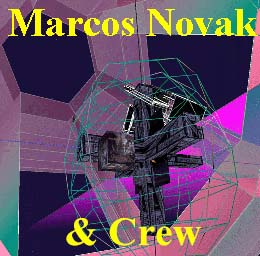
DANCING WITH THE VIRTUAL DERVISH: WORLDS IN PROGRESS – by Marcos Novak & Friends
“In its present disincarnation, consists of a series of interconnected cyberspace ‘chambers.’ Each chamber is a world unto itself, but each chamber has portals to every other chamber, forming a fully connected lattice. As a work, it is non-hierarchical, non-teleological, and inherently open-ended. A person navigating through these chambers is free to explore a series of landscapes and to discover their apparent or hidden features. It is unlikely that anyone, myself included, will ever exhaust the variety of subtle algorithmic wonders that may be encountered, since they are intimately related not only to the logic of their programs, but to the unforeseeable circumstances and patterns of each person’s passage through the spaces.” -M.N.
Supercircuits provides the world’s smallest video cameras, transmitters and recorders.

Survival Research Laboratories (SRL) was conceived of and founded by Mark Pauline in November 1978. Since its inception SRL has operated as an organization of creative technicians dedicated to re-directing the techniques, tools, and tenets of industry, science, and the military away from their typical manifestations in practicality, product or warfare. Since 1979, SRL has staged over 45 mechanized presentations in the United States and Europe. Each performance consists of a unique set of ritualized interactions between machines, robots, and special effects devices, employed in developing themes of socio-political satire. Humans are present only as audience or operators.

Tomorrow’s Women in Science and Technology (TWIST) was an Austin, Texas-based non-profit corporation. Their mission was to promote science and math education and career planning for girls and women. TWIST’s volunteer staff is composed of Austin-area scientists, engineers, librarians, business people, teachers, writers, artists, and parents working together to achieve TWIST’s goals.

Zilker Internet Park specialized in connecting both small and home businesses to the Internet.
The background material for this page is derived from an archived page on the Internet Archive Wayback Machine.
Hexwalker
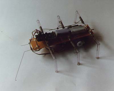
Hexwalker was built from a kit produced by M & T Systems in Huntington Beach California.
The body is made of perforated circuit board material. It has three R/C type servos driving the legs and a Basic Stamp for a brain. Antennae on the front sense obstacles and, after a few steps in reverse, send the creature off in another direction. The method used to obtain the alternating triangle gait is ingenious in its simplicity in that it can do with three servos what usually takes at least three per leg.

Top-view of M & T Systems built-from-kit Hexwalker.
Top-view of M & T Systems built-from-kit Hexwalker.

Don Colbath holding the M & T Systems built-from-kit Hexwalker.
Don Colbath holding the M & T Systems built-from-kit Hexwalker.
Don Colbath, who built this kit reports, “I was not totally happy with the construction methods and materials used and decided to build my own body and legs to attach to the existing servos and brain. This has not turned out to be as easy as I imagined and my “Hexwalker Mark II” is still undergoing refinements. My ultimate goal is to enlarge my version to about coffee table size then later to a size that a person could take a ride on. Stay tuned for future announcements.”
The background material for this page is derived from an archived page on the Internet Archive Wayback Machine. Some links may have been added, removed, or updated.
RoboFest 7 Volunteers

- The Robot Elite Unit
- Max Aghili
- John Fisher
- Drew Glass
- Tammy Gomez
- Bob Izenberg
- Javier Lozano
- Betsy McCutcheon
- Bret Pettichord
- Jeremy Rutland
- Dawn Smith
- Lara Thompson
- Ted Tudor
- Delia Vasquez
- Gustavo Villareal
The background material for this page is derived from an archived page on the Internet Archive Wayback Machine.
RoboFest 7 Film Festival
“Robot Invasion of Dobie Theatre”
September 14-15, 1996
. 16mm print.")
The Day the Earth Stood Still directed by Robert Wise (1951). 16mm print.
The Day the Earth Stood Still directed by Robert Wise (1951). 16mm print.
. 16mm print.")
Forbidden Planet directed by Fred M. Wilcox (1956). 16mm print.
Forbidden Planet directed by Fred M. Wilcox (1956). 16mm print.
. 35mm Director's Cut")
Blade Runner directed by Ridley Scott (1982). 35mm Director's Cut
Blade Runner directed by Ridley Scott (1982). 35mm Director's Cut
| The Robot Film Festival will feature three films with the common theme of robots. From the 50’s era of classic sci-fi come the first two entries both of which will be 16 mm prints. The Day The Earth Stood Still is a 1951 release and is in black and white. Starring Michael Rennie, Patricia Neal, Hugh Marlowe, Sam Jaffe, Billy Gray and directed by Robert Wise. Robert Wise directed dozens of pictures. An early example of his work was Born to Kill (1947). His later credits include The Andromeda Strain (1970) and Star Trek The Motion Picture (1979). “Gort, Klaatu Birada Nikto” is the famous line uttered in this film by Michael Rennie who plays Klaatu. (Or something very close to this line.) Gort is an extremely large and powerful robot with the ability to destroy the Earth. Michael Rennie is just along for the ride and to warn the citizens of Earth that they are not alone in the Universe. The second sci-fi classic is Forbidden Planet a film in Eastman Color released in 1956. Directed by Fred M. Wilcox and starring Walter, Pidgeon, Anne Francis, Leslie Nielsen, Harry Harvey Jr., Earl Holliman, Morgan Jones, Jack Kelly , Roger McGee, and Peter Miller. Fred Wilcox’ other film credits include Lassie Come Home (1946) and I Passed For White (1960). Forbidden Planet introduced us to Robby the Robot probably the most recognized robot of the 50’s sci-fi movie classics. In this film Dr. Morbius (Pidgeon) and his daughter (Francis) insist on remaining on the relatively barren planet Altair IV. When a rescue mission arrives led by Commander Adams (Nielsen) Dr. Morbius warns them that their lives are in danger and that they should leave. They don’t listen and of course strange things begin to happen just like Dr. Morbius warned. Robby is pretty much just a household servant but he’s extremely loyal to his owners. Both of these films will be shown on Saturday the 14th as matinees. The third film of the festival will be shown on Sunday afternoon. The Day The Earth Stood Still will be shown at 2:00 p.m and Forbidden Planet will be shown at 4:00 p.m. Finally to cap off the weekend of the film festival and RoboFest 7 is perhaps the best film about robots ever made. At least that’s our opinion anyway. Blade Runner the 1982 release directed by Ridley Scott will be shown in the 35 mm “Director’s Cut” version. This version is Scott’s vision for what Blade Runner should have been and not what was officially released that year. If you’re a fan of the original movie and you haven’t seen this version on the big screen – you have to see it now. Ridley Scott whose direction credits have included some of the most powerful films of the past two decades brought his dark foreboding vision of Los Angeles in 2019 alive in this film. With an exceptionally good cast of Harrison Ford, Rutger Hauer, Sean Young , Edward James Olmos, M. Emmet Walsh, Daryl Hannah, William Sanderson, Brion James, Joe Turkel, and Joanna Cassidy, Blade Runner became a cult classic almost overnight. The story is based loosley [sic] on a novel by Philip K. Dick called “Do Andriods Dream of Electric Sheep?”. The film screenplay was written by Hampton Fancher and David Webb Peoples and the haunting music score was composed by Vangelis. Ridley Scott’s other movie credits include Alien (1979), Black Rain (1989) and Thelma & Louise. The robots in this film are actually called replicants or artificially created humans. These replicants are quite sophisticated and appear very human like; so much so that it takes a special trained police person with special tools to identify them. This kind of police person is called a “Blade Runner”. The reason the Blade Runner force exists is because of a nasty little incident where replicants killed humans. That of course violates Asimov’s robot principals and is just not acceptable behavior in a robot, therefore all replicants are banned from earth. They are now only serving as slave labor in off world colonies. Deckard (Ford) is a retired Blade Runner who is forced back into action when 5 replicants, hijack a ship back to Earth with questions about their incept dates. The replicants want answers to the same questions we all want. “How long do we have to live?” “How can we live longer?” Rutger Hauer, Joanna Cassidy, Daryl Hannah and Brion James play the replicants who find life so precious that they risk meeting their maker. For real hardcore Blade Runner fans, may we suggest that you read K.W. Jeter’s excellent novelized sequel to the movie adaption. Blade Runner 2: The Edge of Human offers good insights to what might have happened after the movie. Another great book is Future Noir: The Making of Blade Runner by Paul M. Sammon with behind the scenes coverage of the film from day one. Blade Runner will be shown at 5:30 on Sunday afternoon. All of the films will only have one showing during the festival. Admission prices are $3.50 for each film. |
The background material for this page is derived from an archived page on the Internet Archive Wayback Machine. The text of the original has been preserved without editing for spelling or grammar. Some links may have been deleted whereas the others may have been updated.